
A few weeks ago I participated in the 7th edition of Tokyo's self-made OS meetup (自作OSもくもく会). This event was held at Cybozu offices in Nihonbashi which are quite colourful and have great views.
During the event there were lots of presentations that touched topics such as file systems, UEFI, kernel page handling, or memory allocation algorithms. I also gave a talk on how to debug the TOPPERS FMP real-time operating system on QEMU.
Sunday, July 30, 2017
Monday, July 24, 2017
Adachi fireworks 2017
A few days ago, I went to see Adachi's fireworks (hanabi 花火 in Japanese), famous for being the first of the year in Tokyo (Adachi is a ward in the north of Tokyo).

The fireworks are launched from the south bank of the Arakawa river near Kita-Senju station. However, I suggest watching them from the north bank since it's less crowded and the views are fantastic as well. Go to Umejima station and follow the red path to get a nice viewing spot.

The place does get crowded but unless you are going with a big group of people, you shouldn't need to go early to secure a spot. We were 4 people and arriving at 19:00, just half and hour before the fireworks, would have been completely fine.

About 12,000 fireworks were launched in just an hour (19:30 to 20:30). Some of them were really impressive and looked huge. I took lots of pictures with my phone, some of them were blurry but some were ok.

Sometimes pieces of the fireworks would fly and reach our viewing spot. I suggest you bring some sunglasses to protect your eyes from the dust and objects coming down. It had been a while since I last went to a fireworks festival, and it was a great experience.
Monday, July 17, 2017
Blinking an LED with a simple PIC microcontroller
There are many different PIC microcontrollers. Some of them are powerful enough to be used with an arduino-like framework (pinguino) and others are much more constrained. For the former, I suggest using this PIC18F2553 I/SO evaluation board. For the latter, I suggest using a PIC12F675 I/P (or a reference kit). Despite being small and cheap, the PIC12F675 can be powerful enough for many simple applications. Let's take a look at its specs:

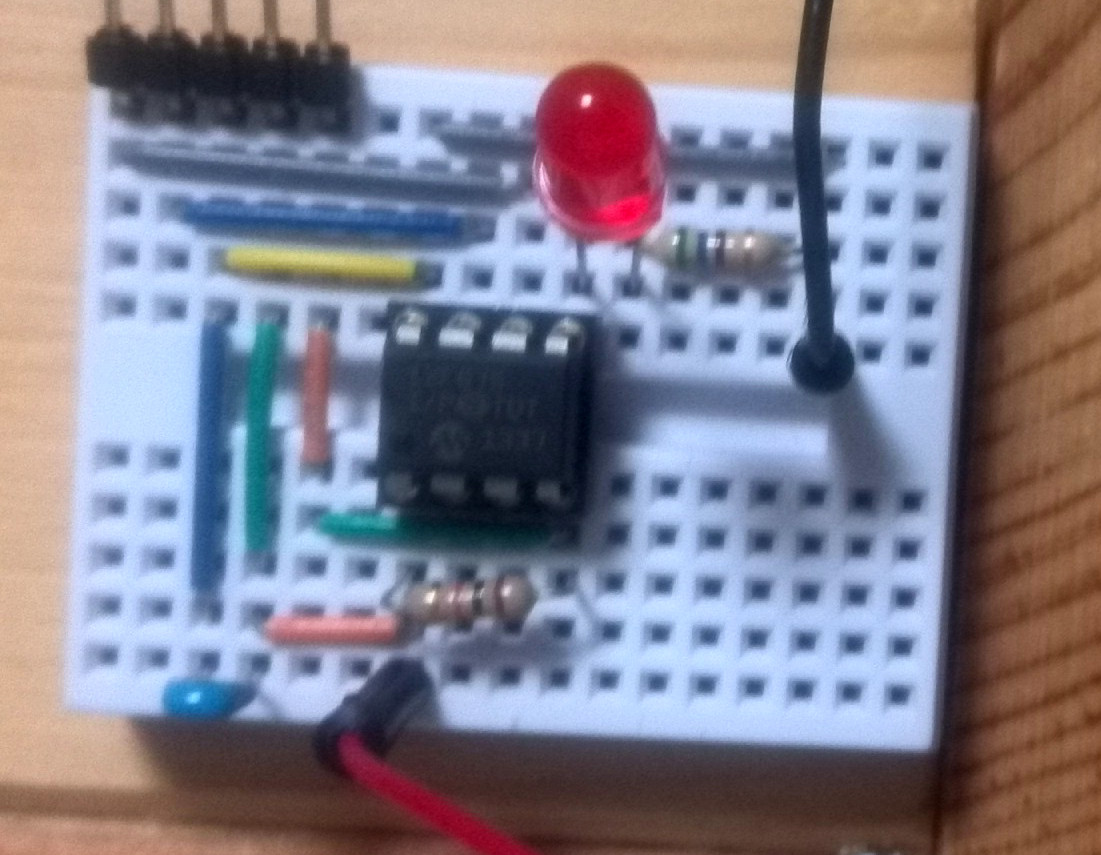
Then, prepare a circuit like the one in the picture on a breadboard. The PIC12F675 contains an internal oscillator so you don't need to supply one. Here we are just connecting the GP2 pin to an LED with a resistor. Additionally, we connect VPP to VDD through a 10kohm resistor and VDD to VSS (ground) with a 0.1uF for programming the chip with Pickit3.

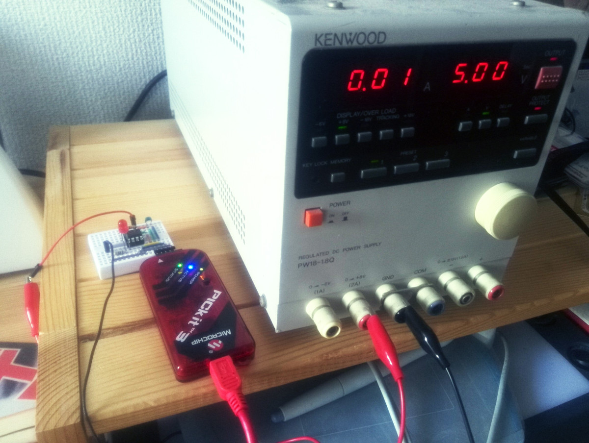
Build the example source code provided by Paolo Rognoni with the MPLAB-X IDE. Connect the board to a 5V power supply and program it with a Pickit3.
Important: if you just bought the Pickit3 and get a "Connection failed" error and a RED status LED, the firmware in your Pickit3 may need an update. In that case, download the Pickit3 programmer application (I had to use v3.10) and open it with the Pickit3 unplugged. Plug it in and click Tools > Check communication. Hopefully it will be connected. Next, click on Tools > Download Pickit operating system, and choose 'hex' to write onto pickit3. Then, click on Tools > Revert to MPLAB Mode and exit the application (if it says no permissions for writing, change the folder permissions to writable). Finally, start MPLAB IPE program (already installed with MPLAB X), click "Connect" and it will update the firmware for you.
- 10-bit A/D converter (4 channels)
- 6 GPIO pins
- Timers
- Analog comparator
- Memory (ROM: 1K words, RAM: 64B, EEPROM: 128B)
Then, prepare a circuit like the one in the picture on a breadboard. The PIC12F675 contains an internal oscillator so you don't need to supply one. Here we are just connecting the GP2 pin to an LED with a resistor. Additionally, we connect VPP to VDD through a 10kohm resistor and VDD to VSS (ground) with a 0.1uF for programming the chip with Pickit3.
Build the example source code provided by Paolo Rognoni with the MPLAB-X IDE. Connect the board to a 5V power supply and program it with a Pickit3.
Important: if you just bought the Pickit3 and get a "Connection failed" error and a RED status LED, the firmware in your Pickit3 may need an update. In that case, download the Pickit3 programmer application (I had to use v3.10) and open it with the Pickit3 unplugged. Plug it in and click Tools > Check communication. Hopefully it will be connected. Next, click on Tools > Download Pickit operating system, and choose 'hex' to write onto pickit3. Then, click on Tools > Revert to MPLAB Mode and exit the application (if it says no permissions for writing, change the folder permissions to writable). Finally, start MPLAB IPE program (already installed with MPLAB X), click "Connect" and it will update the firmware for you.
An oil painting after so many years
When I was a teenager, I used to attend an oil painting class not far from my home in Renedo. During that time, I copied a few famous oil paintings such as Gustave Caillebotte's Le pont de l’Europe. After more than 15 years, I decided to make a new oil painting. The problem was that I had forgotten almost everything. Or that's what I thought. In fact, as I started reading and during the painting process, I was able to recall most of the things I used to know. All that information was still there in my brain, just a little bit rusted!.

I began by coating a canvas board in dark green colours. Usually, a canvas made of linen is best, but this was kind of an experiment so I just used a canvas board from the 100 yen store Daiso. After the green layer dried, I drew the line work on top of it. This time I just copied a portrait that I found on a random website.

It took me some time to recall the names of the oil paint colours that I used to use. For the skin tones, I had to do some research and ended up using ultramarine blue, yellow cadmium, red cadmium and titanium white.

My first tries were really horrible. I had to let the painting dry and redraw everything again for a few times. Instead of applying paint all over, I should have put special emphasis on getting the shapes and values correct at first.

After some iterations, I was finally getting a bit closer to the portrait I was copying from. The woman looks different but here I wanted to focus on recalling the colouring process.

The end result was a small success compared to the initial tries. I learned a lot from my mistakes and it was also useful to know how far I am from being a good painter. I decided to leave the painting untouched, and I'll try to use all the learned lessons for the next one.
Shizuoka Hobby show 2017
In May, I attended the most important event in the world about plastic models: the Shizuoka hobby show. Shizuoka is the place where Tamiya was born, and is easy to reach by Shinkansen, although this time I used the cheaper Tokaido line.

The place was divided into two parts. One part was composed of commercial booths where companies were introducing their latest model kits. Doi-sensei held a nice workshop on figure painting using Turner Acrylic Gouache at the Model Art magazine booth. There was also a bookstore where I bought an awesome book titled 機械昆蟲制作のすべて (all about building machine insects).

The other part was composed of hundreds of tables where plastic model fans were exposing their dioramas and models. There were amazing pieces of art, and I learned a lot from them. There are many different genres in this hobby, and I kind of liked this kind of dioramas representing Japanese street scenes from the Shōwa era.

It was actually on the fans side where I met the author of 機械昆蟲制作のすべて who took the time to sign my book with this beautiful drawing. Thanks a lot!
Day trip to Karuizawa from Tokyo
Last May, I had some days off and I decided to visit Karuizawa. The only thing I knew about it was that John Lennon used to stay over with his family during the summer holidays. Karuizawa is very easy to reach from Tokyo. Using the Shinkansen, it only took me about 1h15 to get there.

Although the main roads were full of tourists and souvenir shops, there were also quiet neighborhoods composed of single houses with wide backyards that most probably only very rich people could afford. The presence of Christian churches, such as the Shaw Memorial Church above, was also notable.

I went past the Shaw Memorial Church and kept walking for a while until I ended up climbing a little mountain. The hike is really nice but make sure you bring some bells to avoid accidents with bears. I met very few people on my way up.


The views from the top are impressive and you can see the famous, and still, active volcano Mt. Asama which is near Karuizawa. By the way, Karuizawa is in Nagano prefecture but very close to the border with Gunma prefecture.


After the hike, I was a bit tired so I had some quality soba and a cup of tea nearby just before heading back to town on this colorful bus. Then, after some walking around the major road and buying some souvenirs I returned to Tokyo by Shinkansen. A really nice day trip.
Thursday, July 13, 2017
DIY mini drill press and router table all-in-one
I bought a Dremel 4000 rotary tool about 4 years ago. However, during all that time I had only used it a few times. One of the problems with the tool is that it's kind of hard to be precise when you use it free handed.
Then, I saw this awesome video on Youtube a few weeks ago and I thought: "I have to built my own!". The design is very well thought and contains some clever ideas. It is also simple and can be made with common tools and materials. I built mine at Kitewa, guided by the experience of its friendly owner Tim.

On one side, it is a drill press. A lever is used to push the Dremel down towards the piece of wood where you want to make a hole. Then, a extension spring connected to the back of the Dremel's board brings it back to its original position. The Dremel tool is hold in place by using two stainless-steel hose clamps. The main body parts are connected through 4mm screws and I used countersinks to make sure the surface was smooth. Another key tool for achieving nearly perfect right angles was the combination square.

On the other side, it is a router table. The Dremel's board has an insert nut on the right edge that allows us to lock its position with a knob. The groove where the knob slides down was made with the help of a plunge router. The design also includes a convenient fence to ensure that we sand or cut to the specified width.

Conclusions: the build took only two days, specially thanks to Tim. During the process I made multiple mistakes: the wood I used was a bit weak, specially for the base; the first extension spring that I bought didn't have enough strength to bring the Dremel back; and I made some holes in the wrong places. However it was overall a very satisfying learning experience for me.
Sunday, July 2, 2017
Writing an oscilloscope frontend with PyQT
In previous posts, I talked about two DIY oscilloscopes that I had built (not dessigned): one based on Arduino and another one based on a dsPIC controller.

Although building my own DIY oscilloscope was fun, I had always wanted to get a real one. A few months ago I decided to buy a used one on Yahoo auctions. In particular, it was an Iwatsu BRINGO DS8812 digital oscilloscope (DSO).

Although there were good oscilloscopes for lower prices, the DS8812 fitted all my requirements:

The only problem that this oscilloscope had, and the reason for its low price, was that the right menu was hard to see. I tried disassembling the oscilloscope and touching different connections but I wasn't able to improve it. For that reason, I decided to create a GUI interface to control and visualize the oscilloscope remotely through the RS-232C interface.

In order to control the oscilloscope, a cross serial cable was required. In my case, I already had a straight serial cable so I only had to buy a null-modem converter which worked great.
The most tricky part was passing the appropriate parameters to the serial terminal. Picocom is my favourite serial terminal, and these are the parameters I used.
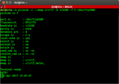
With that in place, I finally managed to get a response from the oscilloscope using the command "DATE?" (commands that end with a question mark represent requests to the oscilloscope).

I programmed the frontend using PyQT (Python bindings for the QT GUI library). I found the QT designer to be particularly easy to use and robust. The source code is on my github account and it uses pyserial for communicating with the oscilloscope, and matplot for displaying waveforms.

Here is a snapshot of two square waveforms on each channel. The app is not very sophisticated but it does its job and can be easily extended in case I need more functionality.

For example, here I implemented an FFT view of the acquire waveforms. This was a paid functionality on the original oscilloscope.
Conclusions: I'm glad that I got a oscilloscope that I could controll remotely. Now I can easily store waveform data, analyze it or save it as an image file. I really enjoyed working with PyQT and the QT designer. They are very powerful and easy to use. Last but not least, I summarized my "endeavour" in a few slides and presented this project at OSunC in Kawagoe.

Although building my own DIY oscilloscope was fun, I had always wanted to get a real one. A few months ago I decided to buy a used one on Yahoo auctions. In particular, it was an Iwatsu BRINGO DS8812 digital oscilloscope (DSO).

Although there were good oscilloscopes for lower prices, the DS8812 fitted all my requirements:
- Cheap (10,000yen, about 78 euro).
- Small size, because my workspace was getting full of devices.
- Enough bandwidth, channels, sampling rate and memory length.
- DC~100MHz, 2 Channels, 500MS/s, 100kword/channel
- A remote control protocol (through RS-232C) that was documented.

The only problem that this oscilloscope had, and the reason for its low price, was that the right menu was hard to see. I tried disassembling the oscilloscope and touching different connections but I wasn't able to improve it. For that reason, I decided to create a GUI interface to control and visualize the oscilloscope remotely through the RS-232C interface.

In order to control the oscilloscope, a cross serial cable was required. In my case, I already had a straight serial cable so I only had to buy a null-modem converter which worked great.
 $ picocom -c --omap crlf -b 115200 -f h /dev/ttyUSB0
    --omap crcrlf: outputs CR/LF instead CR (set osc to CR/LF delimiter)
    -h: enables RTS/CTS
    -c: local echo
The most tricky part was passing the appropriate parameters to the serial terminal. Picocom is my favourite serial terminal, and these are the parameters I used.

With that in place, I finally managed to get a response from the oscilloscope using the command "DATE?" (commands that end with a question mark represent requests to the oscilloscope).

I programmed the frontend using PyQT (Python bindings for the QT GUI library). I found the QT designer to be particularly easy to use and robust. The source code is on my github account and it uses pyserial for communicating with the oscilloscope, and matplot for displaying waveforms.

Here is a snapshot of two square waveforms on each channel. The app is not very sophisticated but it does its job and can be easily extended in case I need more functionality.

For example, here I implemented an FFT view of the acquire waveforms. This was a paid functionality on the original oscilloscope.
Conclusions: I'm glad that I got a oscilloscope that I could controll remotely. Now I can easily store waveform data, analyze it or save it as an image file. I really enjoyed working with PyQT and the QT designer. They are very powerful and easy to use. Last but not least, I summarized my "endeavour" in a few slides and presented this project at OSunC in Kawagoe.
Subscribe to:
Posts (Atom)


 . Information on this blog is provided "as is" without warranty of any kind, either expressed or implied.